| This is documentation for Semarchy xDI 5.3 or earlier, which is no longer supported. For more information, see our Global Support and Maintenance Policy. |
Create Mappings
A Mapping defines the transformation rules to integrate data from one or more source Datastores into one or several target Datastores.
These transformation rules are used by the templates attached to this mapping to generate a complete and optimized data integration process.
Create a New Mapping
To create a new mapping:
-
Click the
 New Mapping button in the Project Explorer's toolbar. The New Mapping wizard opens.
 -
Select the parent folder or project for your new resource.
-
Enter a File Name and then click Finish. The mapping file is created and the editor opens.
Add the Target and Source Datastores
To add the source and target datastores:
-
In the Project Explorer, expand the Metadata containing a source or target datastore (table, flat file, XML file…) that you want to use in your mapping.
-
Drag and drop the datastore from the Project Explorer into the mapping editor.
-
Select this datastore in the editor. In the properties view, set the following properties:
-
Alias: Alias used in the expressions to refer to this datastore. It defaults to the datastore’s name.
-
Use CDC: Check this box to enable consumption of changed data from a source datastore, captured via the CDC feature (see Change Data Capture (CDC)).
-
Enable Rejects Detection: Check this box to enable rejects management on a target datastore. For more details, refer to Rejects Management.
-
Update Key Provider: Defines the key used to identify existing records in the context of updates:
-
Manual Definition: Select this value to define manually the columns to use for the key. Select each column on the datasource and click the
 button to add it to the key’s definition.
 -
Or select an existing constraint from the Metadata.
-
-
Staging Area: Select the datastore to use as the staging area. This option is useful to benefit from another datastore’s transformation capabilities that are not available on the current datastore (for example to use SQL functions in a mapping that involves a JSON or XML file).
When defining a staging area, a block representing the Load process template is automatically added to the current datastore. -
Tag: Add a tag to the table (used in process templates).
-
Description: Free form text.
-
In the Advanced properties section:
-
The Integration Sequence property specifies the order in which tables without any mutual dependencies must be loaded.
-
The Order property defines the order of a source datastore in the
FROMclause generated when loading a target.
-
-
-
Repeat the same operations for all datastores from which data will be extracted (the sources).
-
Repeat the same operations for all datastores into which data will be loaded (the targets).
-
Press Ctrl+S to save the mapping.
Link Datastore Columns
To create a link between 2 datastores:
-
Select a column from a source datastore in the mapping diagram.
-
Drag this column onto another source column in the mapping diagram.
-
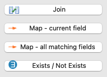
Release the mouse button. You are prompted to select the type of link to create:
-
Join: Creates a new join between the two datastores. For more details, refer to Join Sources.
-
Map - current field: Creates a mapping (source-target link) between the two columns.
-
Map - all matching fields: Creates a mapping (source-target link) between the two columns and between each other group of source and target columns having the same name.
-
Exists / Not Exists: Adds an Exists/Not Exists operation to filter data from the source datastore depending on data from the target datastore (see Exists/Not Exists Filters).
-
| You are prompted to select the type of link only if Semarchy xDI Designer detects that several types of links can be created. If only one type of link can be created, the accurate type will be selected automatically. |
When creating a mapping link between datastores, blocks representing the  Load and Load and  Integration process templates are automatically added to the upper part of the target datastore. See Configure Templates Integration process templates are automatically added to the upper part of the target datastore. See Configure Templates
|
Configure Mappings
Once a mapping link has been created between datastores, it can be configured from the Properties view of the mapped column in the target datastore.
The following properties are available:
-
Enable: Enables or disables the mapping.
-
Execution Location: Defines where the mapping is executed:
-
Source: The mapping will be executed by the source datastore.
-
Staging Area: The mapping will be executed in the staging area.
-
Target: The mapping will be executed by the target datastore.
-
-
Use as Key: Select this option to use the selected column as part of the unique key for this mapping in order to identify records for reject management and target records update purposes. Several columns can participate in the unique key in a mapping. These columns can be the same as the columns involved in primary or alternate key constraints for this datastore, or be distinct.
-
Enable Insert: Enables inserting data with this mapping.
-
Enable Update: Enables updating data with this mapping.
-
Aggregate: Select this option if the selected column’s code contains an aggregate expression. Other (non-aggregated) columns will be added to the
GROUP BYclause of the generated queries. -
Tag: Add a tag to the mapping. Tags are used in process templates.
-
Description: Free form text.
Mapping Expressions
A mapping expression describes how the columns from the source datastore are used to populate a column in the target datastore.
| A mapping, filter, or join expression must use the language and functions from the engine that will process it, which is defined by the Execution Location property (see Configure Mappings). In the typical context where the datastore or staging area is on a relational database, expressions are SQL expressions that are valid for the database engine. Literal values, column names, database functions, and operators can be used in such expressions. |
Edit Mapping Expressions
To edit a mapping expression:
-
Either use the Expression Editor:
-
Open the Expression Editor view and make sure the
 lock option is not enabled. If it is enabled, press the
  button to unlock the view.
 -
Select the column from the target datastore for which you want to update the mapping expression.
-
The Expression Editor view is updated and shows the selected column’s mapping expression.
-
Edit the expression and save the editor.
Drag and drop columns from datastores onto the Expression Editor to add them to the current expression. Press the button to lock the content of the Expression Editor to the currently selected element from the mapping diagram.
-
-
Or use the Mapper Tool:
-
Right-click the target datastore in a mapping and select Mapper Tool. The Mapper Tool opens.
-
Select the target column for which you want to edit the mapping expression. The expression is displayed in the edition zone.
-
Edit the mapping expression.
-
Close the Mapper Tool window.
-
Save the editor.
-
|
Think of a mapping expression as an element of the column list in a Examples of valid mapping expressions using SQL syntax:
|
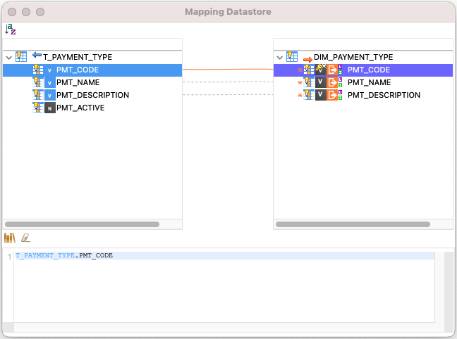
Column Icons
Source and target columns are displayed in the mapping editor with an icon that contains the first letter of their datatype. This icon appears in grey when the source column is not used in the mapping or when the target column is not mapped.
In addition, target columns are tagged with icons to identify their key properties. The various icons and their meaning are listed in the following table.
| Icon | Meaning |
|---|---|
|
The yellow key indicates that the column is part of the key. The white star in the upper right corner indicates that the column is not nullable. If reject management is activated, rows with null values for this column are rejected. The letter represents the column’s data type (I: Integer, V: Varchar, etc.) |
|
The star in the upper right corner means that the column is not nullable and Semarchy xDI checks the null values for this column. |
|
The cross in the upper right corner means that the column is not nullable but Semarchy xDI does not check the null values for this column. |
|
No sign in the upper right corner means that the column is nullable and that Semarchy xDI does not check the null values for this column. |
|
The plus sign in the upper right corner means that the column is nullable but Semarchy xDI checks the null values for this column. |
|
This expression runs in the source. |
|
This expression runs in the staging area. |
|
This expression runs in the target. |
|
These four letters have the following meaning:
|


Configure Templates
Templates in Semarchy xDI are generic and configurable elements used to generate process steps. Templates are automatically added to Stages and target datastores depending on mapping definition:
-
Load templates are used to generate process steps loading data from a source. A
Load template is automatically added to Stages and to target datastores for each source datastore mapped with them and using a different technology. -
Integration templates are used to generate process steps in charge of integrating data into the target. An
Integration template is automatically added to target datastores mapped with at least one source or Stage. -
Stage templates are used to generate process steps that load data in a Stage. A
 Stage template is automatically added to Stages mapped with a source.
 -
Reject templates are used to generate process steps that handle rejects occurring while loading and integrating data. A
 Reject template is automatically added to target datastores for which reject management is enabled.
To configure a template added to a mapping:
-
Select the template’s icon.
-
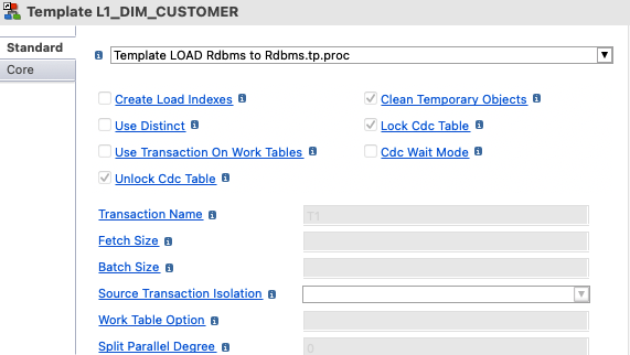
The Properties view shows the template’s configuration. This configuration is composed of:
-
The template file that will be used to generate the process (Template LOAD Rdbms to Rdbms.tp.proc in the example below).
-
The parameters that apply to this template.
-
-
If required, use the drop-down list to select the expected template file to use for this mapping.
To managed the installed templates, refer to Import Templates -
Review and edit template parameters. To modify a parameter:
-
Click the parameter’s label to make it editable.
-
Edit the parameter’s value.
Click the label of a populated parameter to revert to its default value. The most frequent template parameters are listed in Template Parameters
-
Computed Fields
A Computed Field defined on a given datastore is calculated on the fly during mapping execution but is not stored.
To create a Computed Field on a mapping:
-
Right-click a column from the datastore and select Create Computed Field.
-
If the Computed Field is the first one for this datastore: enter a Container’s Computed Field Alias, which defines the label of the container that will contain all Computed Fields for this datastore.
-
A new Computed Field is added to the container named after Container’s Computed Field Alias. By default, this field has the following properties:
-
Name: newField_<sequence number>
-
Expression: <datastore name>.<selected column name>
-
-
Click the name of the Computed Field to edit it.
-
Double-click the Computed Field’s value to edit it in the Mapper Tool.
-
Exit the Mapper Tool and save the editor.
| Computed Fields can be created only on objects having transformation capabilities (RDBMS mostly, with SQL syntax). |
| It is possible to create a Computed Field from another Computed Field, which is useful to chain transformations or operations. |